

Crane Rigging: Understanding Upper Attachment Points and the Load(s) Imposed On Them in a Lift
Continuing the series on crane safety, this article will discuss the complexities of crane rigging, focusing on how the angle of loading affects capacity. In this article, we’ll discuss two additional critical points for consideration: the upper attachment point and the total load. The upper attachment point when loaded properly is subjected only to the total suspended load (i.e., the payload plus additional weight from rigging, equipment, etc.), which can have an effect on load handling activity. Please note that in this article, the examples will deal specifically with a symmetrically loaded two-leg bridle arrangement lifting a load vertically.
The angle of loading ultimately does not have the same affect on the upper attachment point as it does on the bridle slings and attachment hardware at the load. The upper attachment point, if the rigger follows the manufacturer’s guidance for maximum included angle, will only bear the weight of the load, along with any additional rigging hardware, slings, and equipment (i.e., the total suspended load). Understanding what the total suspended load consists of is a critical part of lowering the risk of any load handling activity.
Planning Correctly for Lifting Loads
For upper attachment points, the load is the total weight below the hook and any additional equipment, rigging, and slings added to the lifting configuration. Additional weight cannot be overlooked. In fact, load weights are often different than the calculated or design values. Mill or shop overages in thickness and lengths are not added. Used components may have sediments or process build-ups inside. Items which have been stored outside may accumulate moisture, ice, or dirt. Questions that must be answered to properly rig a load include:
- Is this a theoretical or approximate weight?
- What parts are included in the assembly’s weight?
- Has the actual load weight been measured?
- Can the weight be double checked?
The weights used to plan the lift must be accurate especially when one approaches the capacity limitations of the hoist or crane.
What Load Does the Hook or Upper Attachment Hardware Experience When Lifting a Load Using a Two-Leg Bridle?
With a two-leg bridle arrangement, the sling legs come together at a common upper point. This angle is called the included angle. First, one must look at the hook or attachment hardware and its limitations as far as the maximum included angle. Then, using the information, one can calculate/estimate the total suspended load.
Maximum Included Angle
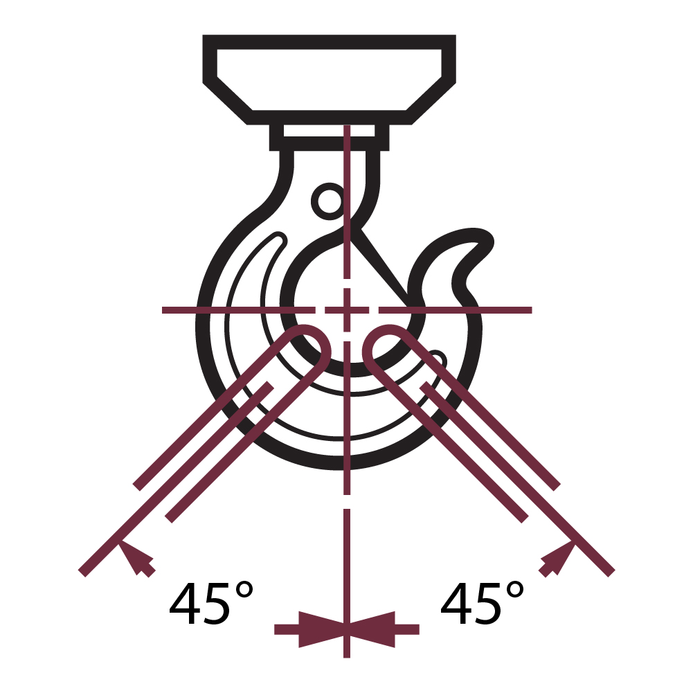
According to ASME B30.10, for single point hoist hooks, the included angle must never exceed 90° (see Figure 1).
For shackles, links and rings, the maximum included angle must never exceed 120° per ASME standards (see Figure 2 & 3).
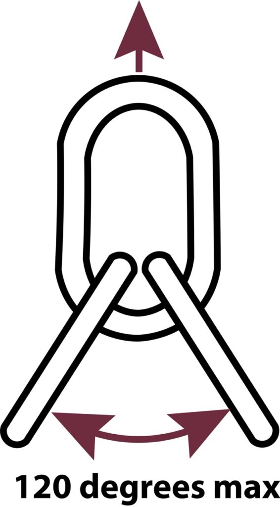
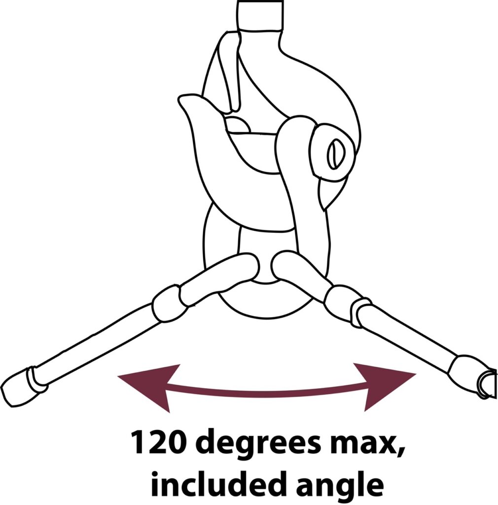
When the load is applied as shown above, there is no reduction in capacity of the hook, collection rings or shackle. The load imposed is not greater than the original load weight plus that of the slings and attachment hardware below the hook, shackle, or ring.
Calculating Total Suspended Load
In the previous article, the vertical share each sling bears was estimated at an angle of loading equal to 90 degrees. To calculate the vertical share each sling bears if the angle of loading is 90 degrees, divide the total weight of the load by the number of legs (in this case, two).
Now, to calculate the total suspended load, multiply the vertical share each sling bears by two and add the weight of the slings and attachment hardware. This amount is the load the upper attachment point will bear.
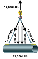
In Figure 4, the upper attachment point bears a load that is no more or less than what is suspended by the attachment point. It is important to note that the total suspended load seen by the upper attachment point is NOT equal to the sum of the tensions on the legs of the bridle.
Dangers of Badly Managed Loads: Center of Gravity Effects
The center of gravity (CG) for a load is the point where the load would balance, or the load is spread out evenly in all directions. For simple shapes, the CG may be located with a few measurements. To have a stable load handling activity or lift, it is necessary to control the load’s CG from the pick or lift point to the set point or the location where it will be placed. Failure to control the load’s CG can result in a catastrophic event.
Always Be Prepared
Thorough planning is the foundation for creating safe working conditions for workers involved in crane operations. Manuals are a key part of this, as they help riggers to plan ahead and prevent issues. Rigorous planning and regular inspections, along with knowing the weight of the load and its center of gravity, can help to mitigate risks and improve operational safety.
Always adhere to standards for safety, conduct timely inspections, and plan meticulously to prevent the catastrophic consequences of crane and/or rigging failures. Consult our experts for more insights in crane and rigging safety.
References:
ASME B30.26 Rigging Hardware – 2015, Reaffirmed 2020
ASME B30.10 Hooks – 2019